

Flange Types, Standards, and Applications: A Complete Engineering Guide
Release Time:
Jul 03,2025
From Welding Necks to Blind Flanges — Understand Designs, Faces, Ratings, and Inspection Essentials for Industrial Piping Systems
Flanges are the most common connection method after welding
They are used where disassembly is required, offering flexibility for maintenance. Flanges connect pipes to various equipment and valves. In systems that require regular servicing during plant operation, detachable flanges are installed.
A flange joint consists of three components: flange, gasket, and bolts. The selection of each affects sealing performance and potential leakage, so each application must be carefully considered. Flange connections are not recommended for buried pipelines and are one of the leading causes of leaks and fires in petrochemical plants.
Flanges come in various types and applications, generally classified by:
Type of connection
Flange face shape
Pressure-temperature rating
Material
Types of Flanges
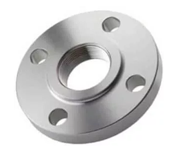
Threaded Flange
Threaded flanges (also called screwed flanges) have an internal thread and are connected to a pipe with a matching external thread. This type of connection is quick and easy to install but is not suitable for high-pressure or high-temperature applications. Threaded flanges are commonly used in utility services such as water lines, drainage, and ventilation systems.
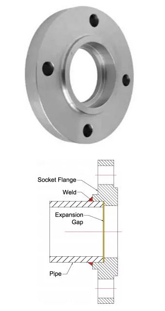
Socket Weld Flange
Socket weld flanges feature a socket into which the pipe is inserted before being fillet welded around the joint. They are generally suitable for small-diameter piping in low-pressure and low-temperature applications.
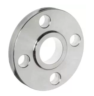
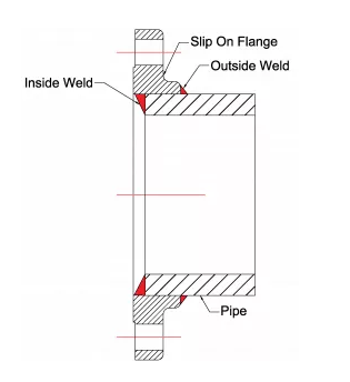
Slip-On Flange
Slip-on flanges have a bore large enough for the pipe to slide through. The pipe is fillet welded both on the inside and outside of the flange. These flanges are used for low-pressure and low-temperature applications and are also available in large sizes for applications like tank nozzles. They are usually forged with a hub, though flat plate versions also exist.
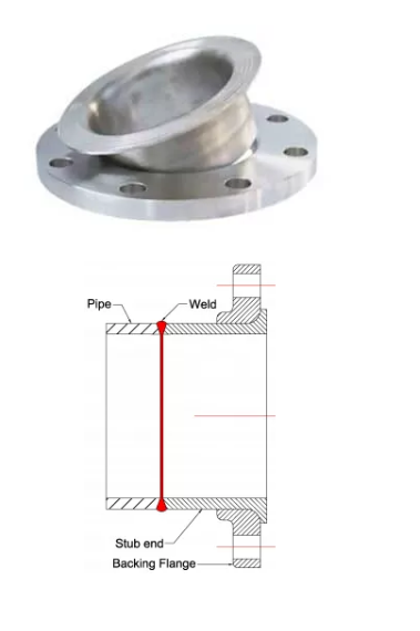
Lap Joint Flange
Lap joint flanges consist of two parts: a stub end and the backing flange. The stub end is butt-welded to the pipe, while the backing flange remains loose and can rotate. The flange material can differ from the stub end, often using carbon steel to reduce cost. Lap joint flanges are ideal for systems requiring frequent dismantling or where space is limited.
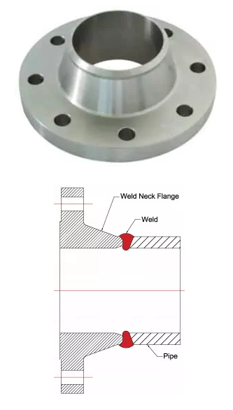
Weld Neck Flange
Weld neck flanges are the most widely used type and are butt-welded to the pipe. They offer the highest joint integrity and are suitable for high-pressure and high-temperature applications. Compared to other types, they are bulkier and more expensive.
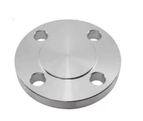
Blind Flange
Blind flanges are solid discs with bolt holes, used to seal the end of a pipe system or vessel opening. They can also serve as manhole covers in pressure vessels.
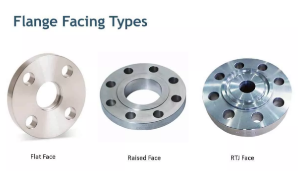
Types of Flange Faces
Flange faces can be classified based on their shape into the following main types:
Flat Face (FF)
Raised Face (RF)
Ring-Type Joint (RTJ)
Tongue and Groove (T&G)
Male and Female (M&F)

Flat Face (FF)
As the name suggests, flat face flanges have a completely flat sealing surface. They are used when the mating flange is also flat, especially in connections to cast equipment, to avoid damage caused by differences in strength between forged and cast materials.
Raised Face (RF)
Raised face flanges have a small raised section around the bore where the gasket is seated. The height of the raised face depends on the flange pressure-temperature rating. For 150# and 300# classes, the height is 1/16", while for classes above 300#, it is 1/4".
Ring-Type Joint (RTJ)
RTJ flanges have a specially machined groove to accommodate a metal ring gasket. They are designed for high-pressure, high-temperature environments to ensure reliable sealing.
Serrations on Flange Faces
As shown in the figure, the flange face has small grooves known as serrations. Flange faces can be either smooth or serrated. The choice between smooth and serrated surfaces depends on the type of gasket used and the fluid environment.

Smooth surfaces are used with metal gaskets, while serrated surfaces are used with non-metallic gaskets. The soft gasket material embeds into the serrated grooves to prevent leakage of fluids or gases through the flange joint.

Serrations can be either spiral or concentric grooves, as illustrated. Concentric serrations are used for fluids with extremely low density. Using spiral serrations for very low-density fluids may cause leakage through the spiral grooves.
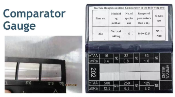
The roughness of the flange face serrations is measured by RMS (Root Mean Square) or AARH (Arithmetic Average Roughness Height). The typical serration roughness ranges from 120 to 250 AARH. A comparator gauge is used to inspect the serration roughness of the flange face.
The figure shows how to use a comparator gauge to verify the serration roughness value.
Flange Pressure-Temperature Ratings (Service Classes)
Flanges are classified according to pressure-temperature ratings, including 150#, 300#, 400#, 600#, 900#, 1500#, and 2500#. Larger diameter flanges, ranging from 24 inches to 60 inches, are available up to the 900# class. As the rating increases, flanges become heavier and are capable of withstanding higher pressures and temperatures.
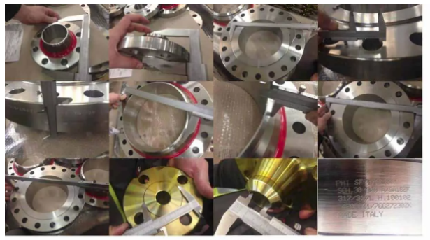
Flange Inspection
When inspecting flanges, the following items should be checked:
Outer diameter (OD) and inner diameter (ID) of the flange body
Hub diameter and thickness at the welding neck
Bolt circle diameter and bolt hole diameter
Hub length
Allowable tolerances are specified in ASME B16.5 and B16.47 standards. The straightness and alignment of bolt holes should also be verified.
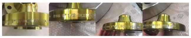
Flange Markings
The following markings are required on the flange body:
Manufacturer’s logo
ASTM material code
Material grade
Heat number
Service rating (pressure-temperature class)
Size
Thickness (face)
Special markings (if any), such as OT (Quenched and Tempered) or W (Weld Repair)
Other News


 – Weldolet, Sockolet, Threadolet & More | High-Pressure Branch Connections")


Subscribe to us for more product information
We will contact you within one working day. Please pay attention to your email.
Contact Info
Add:
Cangzhou City, Hebei Province, China
Share Us

